
Cullen Williams of CATI talks about their Detroit restoration project. You can also check out the video on these innovative technologies.
The Project
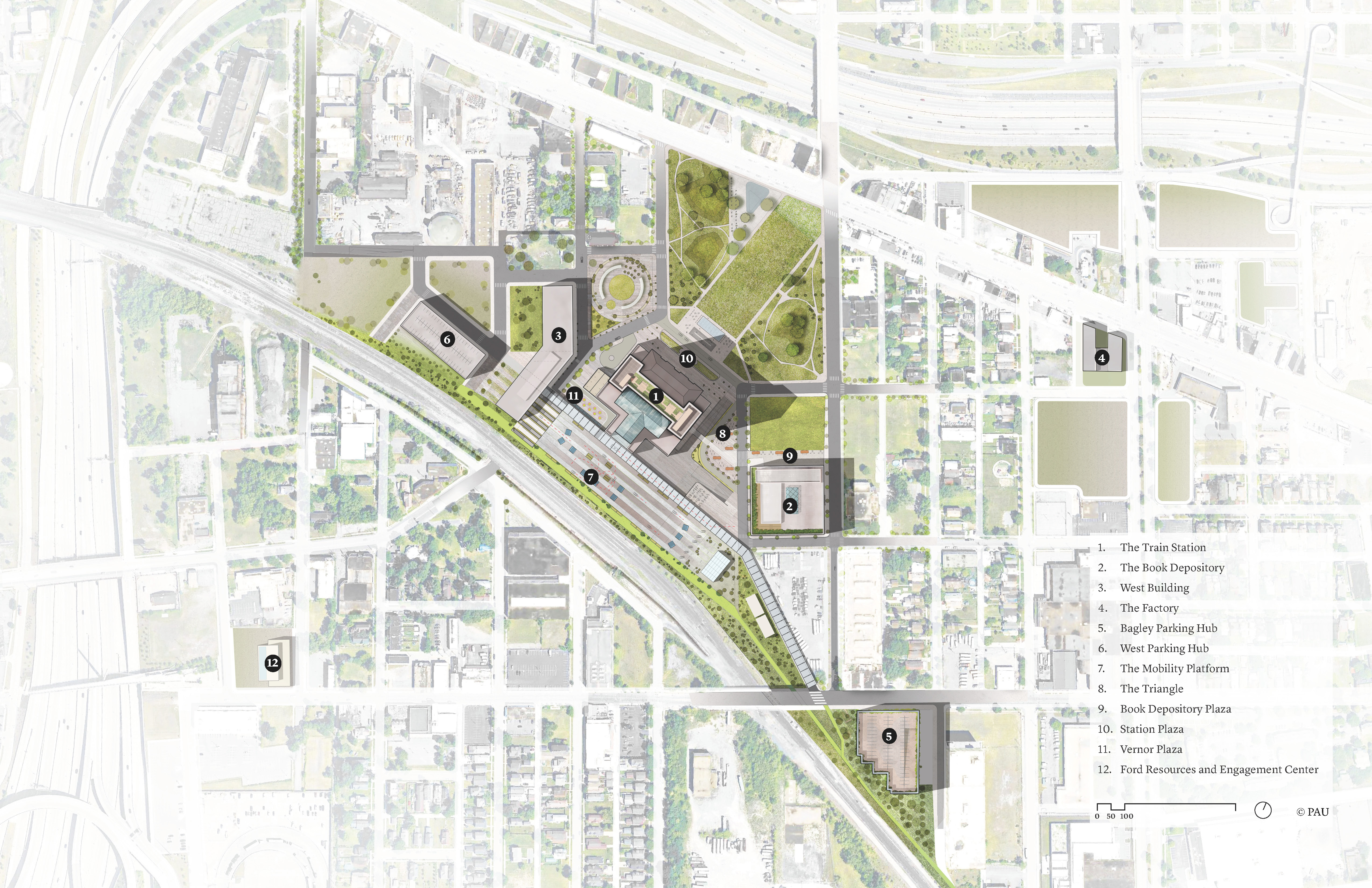
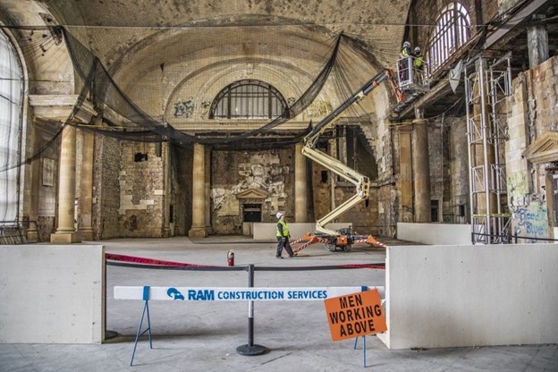
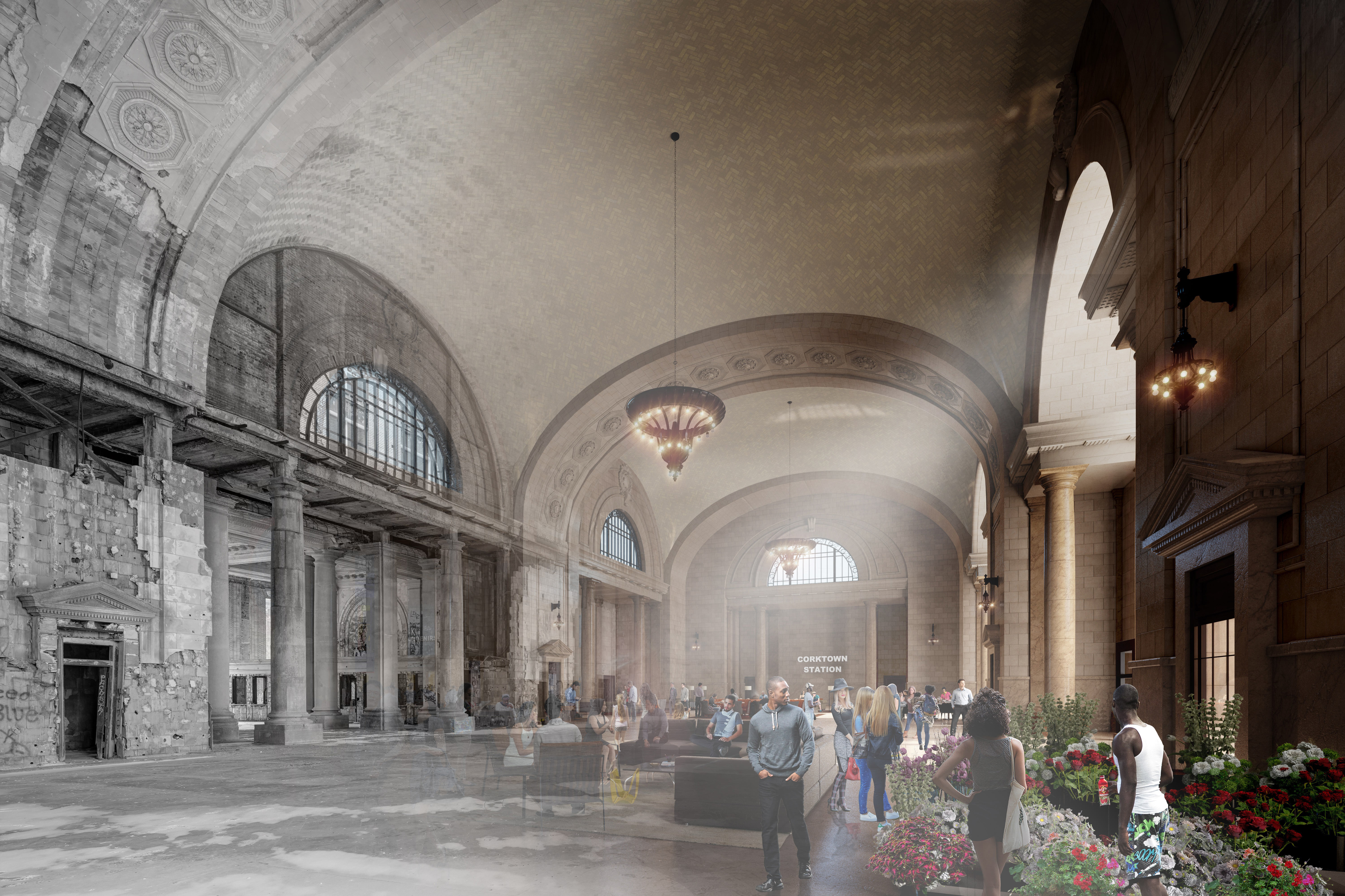
In 2018, Ford purchased an area of Detroit with the idea of restoring the entire campus (Fig. 1) by 2022. One of the larger buildings in this project that encompasses a larger campus, is the old Michigan Central Train Station (Fig. 2). A major focus of this project is the architectural restoration of the building itself — bringing it back to its former glory. The updated plans for the station include a first floor comprised of retail and restaurants that are open to the public, and upper floors converted into office space both for Ford and Ford partners (Fig. 3).
So where does CATI fit into all of this? Ford reached out to CATI to see how we could assist in restoring some of the ceiling and window components. In July 2020, the team at CATI were sent to Detroit to use 3Dscanning technology — a much faster and more accurate process than manual methods — in which the architecture is captured via 3D scanning, the scans are cleaned up and digitized, and tooling is created for the restoration pieces.
Here are a couple of examples of pieces that we scanned and converted into CAD models for use in the restoration process.
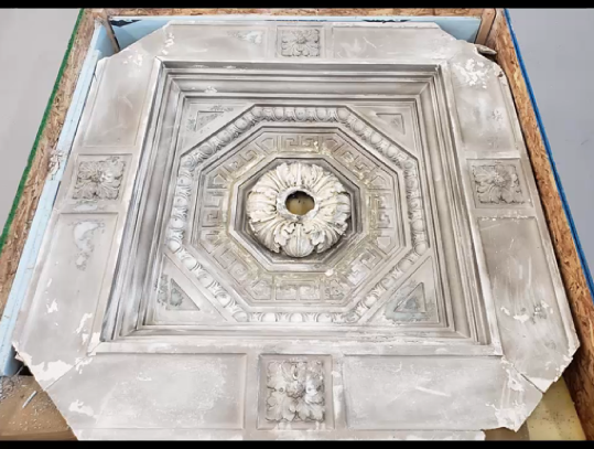
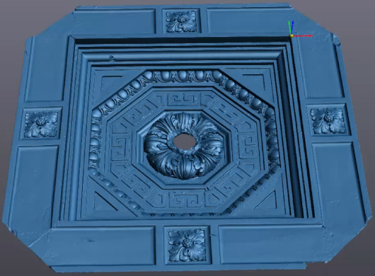
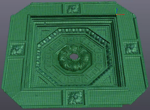
In the first example, you’ll see a ceiling tile (Rosette)that has been scanned and converted to a CAD file. In Figure 4a, you can see a photograph of the actual piece, followed by the mesh file generated by the scanner (Fig. 4b), and finally the 3D CAD file (Fig. 4c) that would be used in the tooling process.
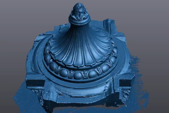
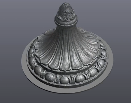
Next, is a ceiling cap. As you can see, the differences between the raw mesh data (Fig. 5a) and the cleaned-up CAD file (Fig. 5b) are pretty significant. This improves the workflow when going to the tooling or molding process.
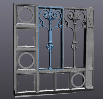
Finally, we scanned and processed some iron works on-site. Notice the more intricate details highlighted and how we were able to easily and accurately convert those into a CAD-friendly format (Fig. 6).
To create the files needed, we used three main 3D scanners from Creaform — the Go!SCAN, the HandySCAN, and the MetraSCAN. These units all operate on the same basic principles of triangulation on reflective targeting.
What does that look like when we go to scan our parts? Let's say we're trying to scan this transmission housing (Fig. 7).
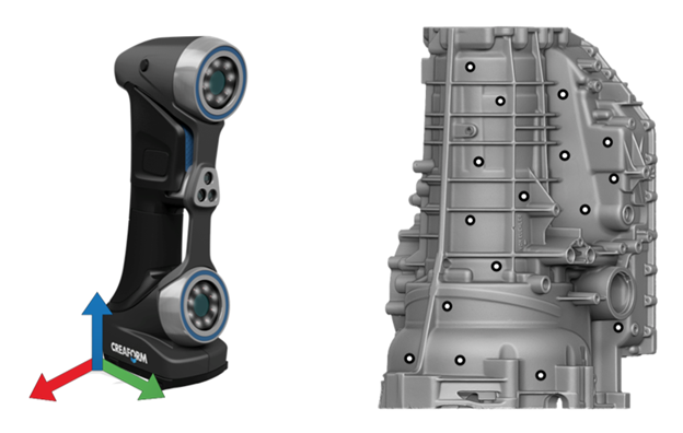
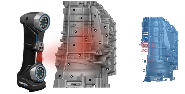
We need two pieces of information to create a usable scan. The first being the surface data itself, but we also need to know where that data is in 3D space. To create this frame of reference, we place reflective targets on the part surface for the scanner to capture and create a frame of reference based on the constellation of targets. Once the reference frame is established, we begin projecting our light source, either lasers or white light (Fig. 8). Byob serving how that deforms on the surface, we can then triangulate that information back into usable surface data referenced off the original item.
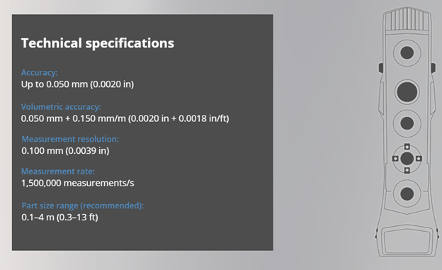
Now let’s take a look at the various equipment we used beginning with the Go!SCAN 3D (Fig. 9). Just like with the HandySCAN, theGo!SCAN needs a reference origin in order to scan, but this piece of equipment uses several different options, not just the targets, to achieve that reference frame. This system is called hybrid positioning. It allows the Go!SCAN to use color and part geometry to track the scan, not just targets. Using the Go!SCAN,we get an accuracy of two thousandths of an inch with a measurement resolution of just under four thousandths of an inch with data acquisition at the very high speed of 1.5 million measurement points per second. We can scan parts ranging from under 0.5 foot to 13 feet in size.
The hybrid positioning of the Go!SCAN allows for very easy scan setup, so we are able to minimize the number of targets needed. So since we were on an active job site, we needed the ability to quickly get in and out which the Go!SCAN handles easily, along with fast measurements and portability. All that was needed was an extension cord with a power source to get the Go!SCAN running quickly.

Next is the HandySCAN (Fig. 10) which uses a blue laser light as its light source. This light source lends itself to much higher accuracy and resolution scanning capabilities. It has an accuracy of nine ten thousandths of an inch and a measurement resolution of the same. With the higher resolution, we can get a little bit smaller on the part size from about 0.15feet up to 13 feet. The 11 blue laser crosses allow for 1.3 million measurement points per second. It's also a metrology-grade piece of equipment and is able to scan a wide variety of surface finishes including very shiny chrome-plated surface finishes.
We brought the HandySCAN for its higher resolution scans for finer details. The powerful blue lasers lend itself to scan flexibility, so where there were different surface finishes, the blue laser technology can easily pick it up. It is very quick to set up and easy to use on an active job site.
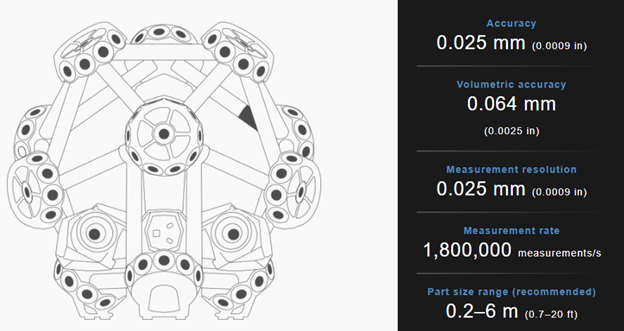
The final piece of equipment we brought was the MetraSCAN 3D(Fig. 11). Similar to HandySCAN, the MetraSCAN uses blue laser technology which results in very similar accuracies and resolutions, however the MetraSCAN is designed for larger volume scans. It is a two-part system with a tripod camera system called the C-Track, as well as the handheld scanner itself.
Using 15 blue laser crosses, it is the quickest of the three units with the ability to capture 1.8 million measurement points per second. It is also metrology certified and provides limitless scanning volume with a portable setup — something very critical on an active job site.
Since some of the large archways that needed to be scanned required a continuous scan over a very large volume, we used the MetraSCAN. The blue lasers were key in scanning multiple surface finishes within the same scan and allowed for higher resolution on fine details.
With the Creaform 3d scanners, we are able digitize what we see right in front of us with all its flaws and import it into software where we can digitally repair it. We then use those digitized files during the restoration process to recreate those physical pieces in their original form. By taking multiple, identical pieces with different areas of damage on them, we are able to combine the files to ensure we have 100 percent good data.
If we can't find an area undamaged on every single piece, or maybe only have one original piece, that's where the art meets the science. We have start playing with the file a little bit more artistically, almost like digital clay, in order to get the restoration done in the most accurate way possible. Having CATI on board allowed Ford to capture that existing conditional information and then fabricate the missing elements. Without it, Ford would have used traditional methods that were inefficient and less accurate.
In an area of Detroit that has a history of being a great hub of technology and innovation, it’s been incredible to see this next generation of scanning technology be a key in helping it come back to life.
You can watch a video on this project here:


